


Increasingly, Salesforce Architects need to be able to work across multiple platforms and understand models of data both in and outside of Salesforce. While Salesforce Architects has always drafted Entity Relationship Diagrams (ERDs) and template data models using industry standard data modelling notation, the declarative interface differentiates relationship types as Lookup or Master-Detail relationships – each with distinctive behavior that is specific to the Salesforce platform.
In this article, we’ll explore more specific data model relationships by unpacking the key terms cardinality and ordinality, as well as exploring standard notation styles such as Information Engineering notation used by Salesforce Architects to express relationships between data tables. Understanding these basic architecture concepts should equip Architects, Developers, and any other technical role with the language to interpret data models across platforms.
How Are Relationships Defined?
Check out the Case data model from the Salesforce Architect’s Data Model Gallery. Notice that this data (and other data models in the gallery) use industry-standard notation borrowed from Information Engineering notation, not Salesforce’s declarative lookup and master-detail relationship types. More precise data model notation helps Architects and Developers understand the specific nature of the data model:

Note: Salesforce enables Architects to declaratively define a number of different relationship types, such as external relationships, to support platform-specific use cases. Familiarize yourself with Salesforce relationship types.
In Salesforce, we refer to data tables or entities as “objects” and data table joins as Lookup or Master-Detail relationships. Using platform-agnostic terminology, we can define the nature of a data model and its entity relationships by expressing cardinality and ordinality.
Cardinality and ordinality express the nature of relationships between data tables. For our purposes:
- Cardinality expresses the type of relationship (i.e., 1:1, 1:M, M:M).
- Ordinality expresses the optionality of that relationship (i.e., optional, required).
Another way to think of this is that cardinality defines the maximum number of times an entity can participate with another entity (i.e., one; many), whereas ordinality defines the minimum number of times an entity can participate with another entity (i.e., zero (optional relationship); one (mandatory relationship)).
There’s lots more to learn about cardinality and ordinality in database design – check out further resources here.
Specific notation styles, such as Information Engineering notation, allow Architects to express cardinality and ordinality in relationships to create a precise model of the data. Understanding cardinality, ordinality, and Information Engineering notation can support you in:
- Understanding data model templates provided by Salesforce Architects.
- Creating specific and descriptive Salesforce data models.
- Interpreting and drafting platform-agnostic data models.
Architects and Developers should be familiar with the following relationship types and notation style leveraged in Salesforce Architecture diagrams:
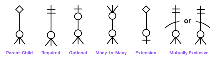
In the following sections, we’ll define each of these relationship types in more detail.
Notating Cardinality and Ordinality
Cardinality expresses the type, or nature, of relationships–defining the upper limit of related records. Three generic types of relationships can be defined, including:
- One-to-one (1:1)
- One-to-many (1:M)
- Many-to-many (M:M)
One-to-one relationships
A 1:1 relationship is used to enforce the exclusive relationship of one record in a data table to one other record in another data table. This less common relationship type may be used to improve performance (depending on querying requirements), to separate sensitive information and improve data security, or to logically group or subtype certain aspects of information from the main data table.
A 1:1 relationship can be expressed using the “extension” relationship notation:
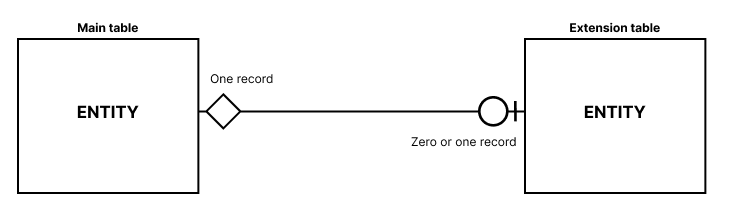
In this notation style, the diamond side of the line denotes the necessary main table, and the circle and line (|) of the line denotes that there can be zero or one related extension table, meaning that the main table can exist without extension table data, but the extension table data must always reference the main table.
One-to-Many Relationships
1:M relationships are the most commonly leveraged relationship and express a conventional “parent-child” relationship. Data table joins (relationships) are typically expressed as parent-child relationships where the “parent” entity (object) can have zero or many related “child” entities (objects).
In Salesforce Architecture notation, cardinality for parent-child relationships is expressed using a solid relationship line with a crow’s foot attached to the child entity (indicating the “many” side). Let’s see how ordinality (whether records are optional or required) is notated in 1:M relationships.
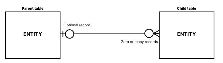
For optional relationships, parent and child records can exist independently of one another, without the necessity of a relationship.
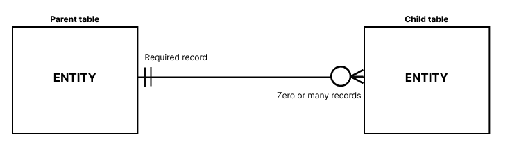
For required relationships as depicted above, a parent record can exist with zero or many related child records; however, a child record must have a related parent record to exist.
Many-to-Many Relationships
M:M relationships occur when:
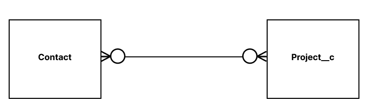
- One instance of Entity A can be associated with many instances of Entity B, and
- One instance of Entity B can be associated with many instances of Entity A.
An example of this could be the relationship between an employee (Contact) and a project (Project__c) they manage. Functionally, an individual employee could be assigned to many projects over time, and a single project could have many employees assigned to it at a given time.
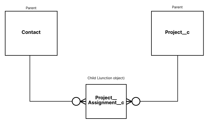
To reconcile this many-to-many relationship, a “junction” object needs to be introduced to define the instance of a particular record of each entity relating to one another (i.e., an individual employee managing a specific project).
M:M relationships are often notated in conceptual models where a lower degree of specificity is required in the model (review conceptual, logical, and physical data models as a refresher on how to model data for different purposes and audiences), and only high-level entities are relevant for the audience.
Final Thoughts
As Salesforce platform Architects, we’re fluent with the different behaviors of lookup relationships vs master-detail relationships. Since these relationship types are specific to the Salesforce platform, Architects must understand how these terms relate to more industry-standard and platform-agnostic relationship types and notations, such as Information Engineering (or “crow’s foot”) notation used in the Salesforce Architect’s data model gallery.
Precise ERD/data model notation styles empower technical stakeholders to understand the specific nature of how data is related, including cardinality (the type of relationship–1:1, 1:M, M:M) and ordinality (optional; required nature) of that relationship.
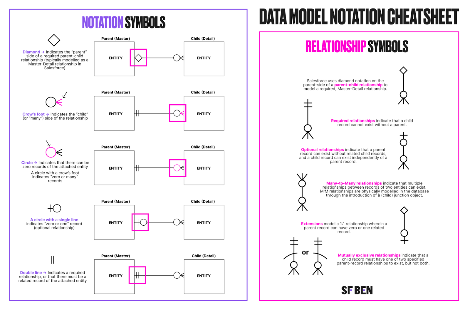
Building fluency with the foundational notations of common notation styles, such as Information Engineering, can help you to more easily understand Salesforce Architecture documentation. The most common notations to commit to memory include:
- Crow’s foot: Indicates the “many” side or “child” entity in a relationship.
- Circle (or zero): Indicates optional records.
- Double lines (||): Indicate required relationships.
If you need a quick reminder on how to interpret Salesforce Architecture ERD notation, take a look at this infographic below!